
This resource is part of a series covering Chemical Process Diagrams:
- Chemical Process Diagrams Part 1: Introduction And Block Flow Diagrams
- Chemical Process Diagrams Part 2: Process Flow Diagram
- Chemical Process Diagrams Part 3: Piping & Instrumentation Diagrams
What Is A Piping & Instrumentation Diagram?
Piping & Instrumentation Diagram (P&ID) (figure 1) is the main design, modification and maintenance reference, and is that it contains all the details of the PFD so when needing to draw a P&ID having the PFD ready will make the job a lot easier to add the extra details for the P&ID, such as control strategies, piping and instrumentation.
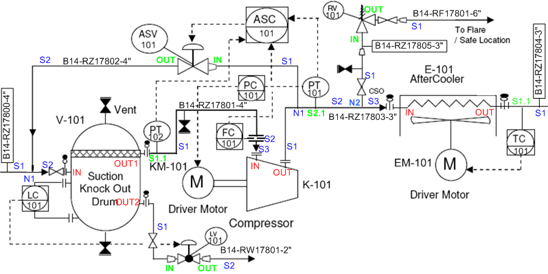 Figure 1: P&ID of anti surge controls of a centrifugal compressor (Teijgeler , 2018)
P&ID Requirements
All P&ID drawings have a number of requirements that must be meet and there are other things that shouldn’t be included (table 1) (The Engineering toolbox, 2020).
| Required | Not Required |
| Instrumentation and designations | Equipment rating or capacities |
| Mechanical equipment with names and numbers | Instrument root valves |
| All valves and their identifications | Control relays |
| Process piping, sizes and identification | Manual switches and indicating lights |
| Miscellaneous – vents, drains, special fittings, sampling lines, reducers and increasers | Primary instrument tubing and valves |
| Permanent start-up and flush lines | Pressure temperature and flow data |
| Flow directions | Elbows and similar standard fittings |
| Interconnections references | Extensive explanatory notes |
| Control inputs and outputs, interlocks | |
| Interfaces for class changes | |
| Seismic category | |
| Quality level | |
| Annunciation inputs | |
| Computer control system input | |
| Vendor and contractor interfaces | |
| Identification of components and subsystems delivered by others | |
| Intended physical sequence of the equipment |
Table 1: P&ID requirements
P&ID’s are very useful for a number of things such as; for training works to demonstrate the process in detail and help keep track of connections between equipment and instruments, for safety and maintenance as the P&ID can be studied for the different process steps and can be used to identify any causes of mistakes or issues, the P&ID is also good at cost estimations as it contains all the specifications required.
P&ID Drawing Conventions: Instrumentation
When drawing a P&ID, the computer software’s will have ready to use symbols of the process equipment, piping and instrumentation, which makes it a lot easier than having to draw everything out and the best method to learn P&ID’s is to become familiar with the symbols. Pining and connection symbols are vital for P&ID’s, as they show the positions of piping and connections and the types of signal that are being used (electrical, pneumatic, data etc.) (figure 2).
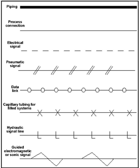
Figure 2: Piping and connection symbols (Kimray, 2020)
Instrumentation (figure 3) is shown in a circular symbol with a tag number (identifies function and type of device) that contains a mixture of letters and number to indicate the measured variable such as flow or temperature, the function of the device such as an indicator or controller the number of the device such as 001 or 002 (figure 4).
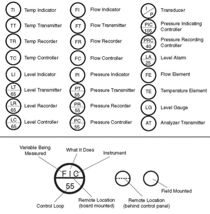
Figure 3: P&ID instrumentation legend (Kimray, 2020)
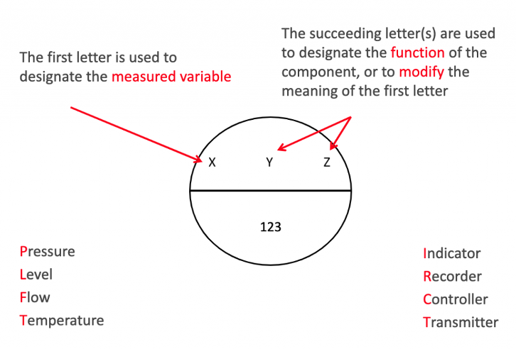
Figure 4: Instrumentation tag number example (Kimray, 2020)
For instrumentation the location of the line (figure 5) indicates where the physical location of the instrument is with a no-line showing the equipment is mounted in the field (can be seen), the solid line means that the instrument is in the control room and a dotted line shows the instrument is mounted out of eyesight
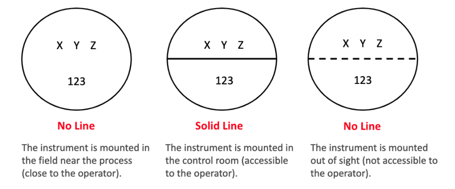
Figure 5: Instrumentation location symbols (Kimray, 2020)
P&ID Drawing Conventions: Control Valves
Control valves (figure 6) are used to control fluid flow, by changing the flow that will be determined by the controller, which can be manually set or automatically set with safety limits imposed so the controller alters the flow without human contact. Control valves consequentially will have a bearing on other conditions such as pressure, temperature and fluid levels as it controls the flow and will have an effect on other conditions.
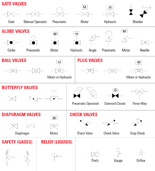
Figure 6: Most common control valve symbols (Kimray, 2020)
P&ID Drawing Conventions: Equipment Symbols
Lastly, equipment symbols (figure 7) such as pumps, tanks, heat exchangers, compressors, reactors and others, will be the basis of the P&ID as all connections, piping and instrumentation will be coming off them and the control strategies will be based keeping the equipment running at the optimum working conditions to be able to produce the maximum amount of product, which will generate more money.
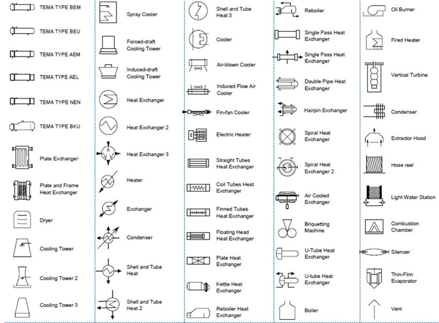
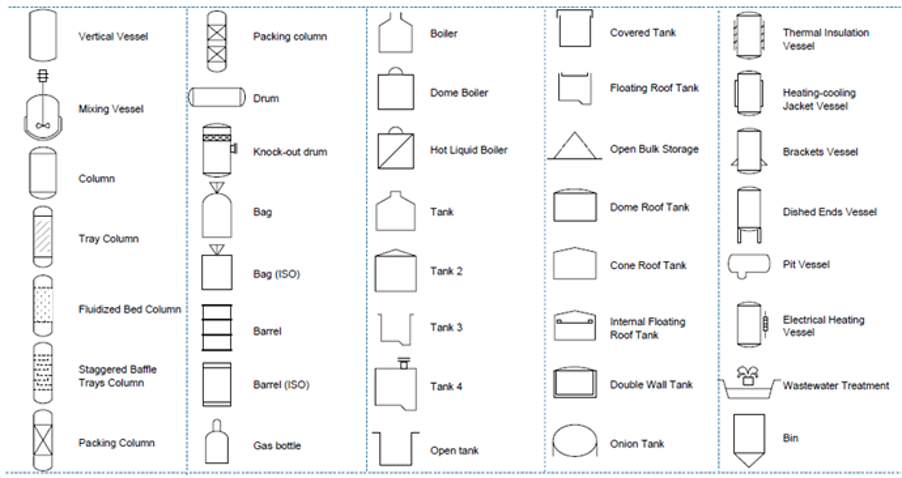
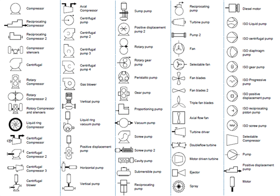 Figure 7: P&ID process equipment symbols (Instrumentation forum, 2018)
Reference
Instrumentation Forum. (2018, June 1). Piping & Instrumentation Diagram. Retrieved from Instrumentation Forum: https://instrumentationforum.com/t/piping-instrumentation-diagram/5007
Kimray. (2020, February 13). How to Read Oil and Gas P&ID Symbols. Retrieved from Kimray: https://blog.kimray.com/how-to-read-oil-and-gas-pid-symbols/
Teijgeler. (2018, June 26). Mapping of a P&ID. Retrieved from Teijgeler: https://15926.org/topics/mapping-pid/index.htm
The Engineering toolbox. (2020). P&ID – Piping and Instrumentation Diagram. Retrieved from The Engineering toolbox: https://www.engineeringtoolbox.com/p-id-piping-instrumentation-diagram-d_466.html

Dr. Adam Zaidi, PhD, is a researcher at The University of Manchester (UK). His doctoral research focuses on reducing carbon dioxide emissions in hydrogen production processes. Adam’s expertise includes process scale-up and material development.’

That first drawing is a PFD, not a P&ID. You’re missing:
– Line sizes
– Line materials
– Pipe Schedule, or Rating
– Valve sizes
– Valve failure action (Fail Open/Closed/Last)
– Equipment sizes and ratings
The list goes on… A P&ID should be a very detailed description of what’s in your process, and be supportive of a HAZOP or PHA. That drawing you have up there is not sufficient in the least.
Hey,
Great spot, you are correct. Figure 1 was more of a ellaborated PFD rather than a P&ID. We have ammended this error and hope that the new Figure 1 P&ID is a sufficient example. Please let us know what you think?
Thanks
Harris Khan