The following article analyses the different techniques involved in producing electricity from biomass systems. This article will outline 4 different biomass systems using 4 different scenarios for each system to calculate and determine the overall efficiency, specific capital cost, and the cost of electricity. Each scenario will be assessed for the individual systems over a specified range of rated power which will be 2.5MWe to 25MWe.
The four different technologies outlined within this report are as follows:
- PyrEng: is the fast pyrolysis (fluidised bed) with compression-ignition engine, including intermediate liquids storage.
- GasEng: atmospheric gasification (fluidised bed) with spark ignition engine, including Tar cracker and gas clean up.
- Integrated Gasification Combined Cycle or IGCC: Pressurized gasification (fluidised bed) with gas turbine combined cycle, including hot as clean up.
- Combust: Combustion (moving grate) with boiler and Rankine cycle.
What Are Biomass Systems and What Advantages do They Have Over Conventional Fuels?
Biomass systems are an alternative to conventional fossil fuels as energy sources. They have multiple benefits over conventional fuels such as the increased scarcity of fossil fuels as well as being less environmentally damaging.
The other advantages come with the introduction of pellets in the early 2000’s. Pellets have high energy densities. They can be easily fed within heating systems.
Increasing government regulation and legislation requiring companies to reduce and even meet targets on greenhouse gas emissions coupled with increasing knowledge and information affecting public opinions on companies have led to better Press for companies who are opting to ‘go green’.
This has led to a large increase in the popularity, use and development of biomass systems by companies as a viable long term option over fossil fuels as energy sources (ATech Electronics, 2019). For example in 2019 there are around 3800 active biomass power plants worldwide with an expected 5600 commissioned by the end of 2027 (ecoprog, 2019).
Methodology
The overall efficiency is the annual net electricity delivered from the plant to the grid
Measured as a percentage and can be calculated using Equation 1.11 below:

Equation 1.11 Equation to determine the overall efficiency of the plant used for each biomass system.
The specified range of rated power is split into 10 ranges. Rated power can be defined as the net power exported by the power plant if it is running at full load.
For each of the rated power ranges an initial biomass wet feed (mB) is assumed which then allows the chemical energy in (Ec) to be calculated using the Heating value (H), which is of the biomass as shown in equation 1.12:
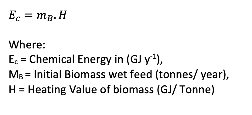
Equation 1.12 Equation to calculate the chemical energy in of the plant for each biomass system.
Once the chemical energy in has been determined the electrical energy out (EE) can be calculated using the chemical energy in (Ec) and the overall electrical efficiency (e) as shown in equation 1.13 below:
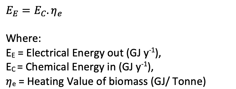
Equation 1.13 Equation to calculate the electrical energy out of the plant for each biomass system.
Conversion Efficiency is defined as efficiency in converting the raw biomass material energy to energy within the intermediary product for example with the PyrEng the energy this means the pyrolyser to the bio oil intermediary bio oil liquid storage. This Is calculated by using a function of the given values.
Generation efficiency is defined as the efficiency with which the conversion of energy within the intermediary product is converted into electrical energy which can be used and transported to the grid. This is also calculated by using a function of the given values.
Rated power (PE) for each scenario and system can then be worked out using the electrical energy out (EE) as seen in equation 1.14 below:
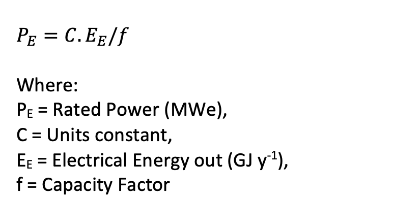
Equation 1.14 Equation to calculate the Rated power for each biomass system.
Capacity factor is calculated using equation 1.15:

Equation 1.15 Equation to calculate capacity factor used in the calculation for equation 1.14.
Once the above has been worked out for each biomass systems and each of its 4 scenarios the economic measures can be calculated.
The specific capital costs (SCC) consist of four different elements known as preparation, drying, conversion and generation.
SCC can be worked out using equation 1.16 shown below:

Equation 1.16 equation to calculate the specific capital costs at each rated power range for each biomass system.
Cost of Electricity (CoE) is then worked out following the determination of the specific capital costs (SCC) and can be calculated using the equations 1.17:

Equation 1.17 equation to determine the cost of electricity at each rated power range for each biomass system.
The total of all system annual operating costs consist of seven elements known as feed production, feed transport, labour, utilities, overheads, maintenance, and annual cost of capital.
Feed preparation includes the reception, handling, screening, grinding and storage.
Overheads are a percentage of the total capital cost.
Feed production is calculated using equation 1.18 below:

Equation 1.18 equation to calculate the feed production costs per year.
When calculating the feed production cost, it is done on a dry basis. The feed rate is given as a wet basis. Wet basis is defined as the mass of moisture divided by the total mass on the product. To gain the dry basis mass the wet basis mass is divided by 2 as an assumption is made that the product is 50% wet basis.
Annual capital costs are the annual cost equivalent spread over the lifetime of the process. As stated above annual cost of capital (ACC) is used in the calculation to determine the sum of annual operating costs and can be evaluated using equation 1.19:
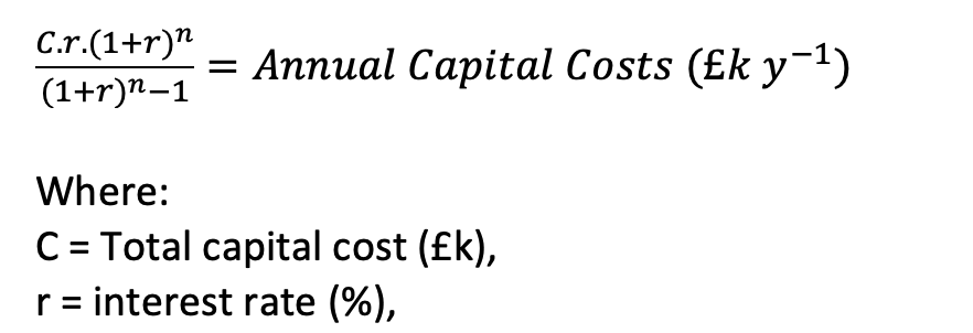
Equation 1.19 equation to calculate the annual capital costs included in the operating costs per annum outlined in equation 1.17.
Learning factors are the reflection in the learning process of new plants and can be defined as the amount capital cost reduces every time the number of plants in operation doubles.
The learning factors can be factored into calculation using equation 1.20 below:
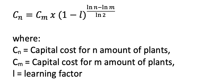
Equation 1.20 equation to calculate the new capital cost including the learning factor.
Wherever a biomass system is described as ‘mature’ the learning factor, l, is set to 0.
Data Analysis & Discussion on 4 Biomass To Energy Systems
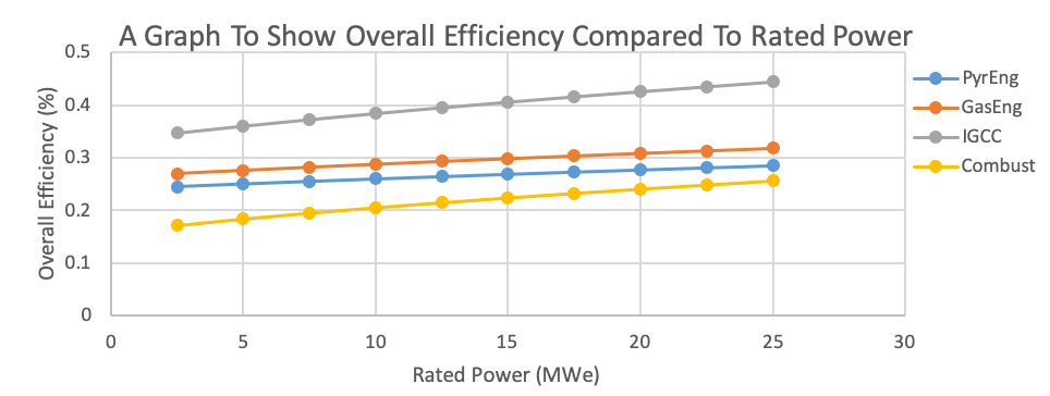
Graph 1.11 Graph to show the overall efficiency compared to the rated power.
Graph 1.11 above compares the overall efficiency (%) between all four systems over the rated power range (MWe).
The Most Efficient Biomass System
IGCC is the most efficient of all the biomass systems over all the rated power ranges. For example, at a rated Power range of 5 MWe the IGCC had an overall efficiency of 0.36% compared to the second-highest of 0.28% for GasEng followed by PyrEng at 0.25% and lastly the Combust at 0.18%. This trend does not change over the rated power range.
How Does an IGCC Biomass System Work?
The IGCC system works by utilising gasification followed by the use of gas clean-up and lastly a gas and steam turbine to create a combined system to allow for a more environmentally friendly, efficient and clean way of creating electricity especially compared to classic combustion systems as seen in graph 1.11 above (Wang, 2016).
How Does an Gasification Biomass System Work?
Gasification is the process in which carbon-based material such as biomass is turned into fuel/ energy without the use of combustion. This is done by incomplete combustion of the biomass feed in an oxygen-deficient area. This leads to less heat being released as compared to a combustion method as gasification packs energy into the bonds whereas combustion releases the energy from the bonds by oxidizing the feed giving off heat (Basu, 2010).
In the gasification process, syngas and ash amongst other intermediary products are converted into a gas.
Once the Gasification process is done gas is cleaned up by removing contaminants including CO2, if carbon capture is used before the fuel is combusted, in the gas turbine phase meaning there is greater heating value in the combustion of the fuel as compared to combustion biomass systems. Moreover, it also leads to less harmful and polluting gases such as mercury and sulphur being combusted with sulphur being one of the lead causes of acid rain. Due to IGCC plants being run at high pressure the efficiency of the removal of the contaminants increases with the capital costs being reduced due to the lower volumetric flow rate of the pre combusted fuel as compared to cleaning the gas at ambient temperature post combustion at a higher volumetric flow rate. This also contains more gases as compared to just fuel which is pre combusted (Wang, 2016).

Figure 1.11 Diagram demonstrating the IGCC biomass system (Mitsubishi Hitachi Power Systems, 2019).
How Does a Rakine Biomass System Work?
Combust is the oldest of the four systems and the least efficient. Combustion systems such as the Rankine System work by utilizing an external heat source such as the combustion of biomass material to provide heat to a closed system containing an operating fluid.
A pump is used to pump high pressurized operating liquid into a boiler where it is heated using the external heat source, in this case combusted biomass material, where the operating liquid undergoes Isobaric heat transfer reaching its saturation temperature and further heated until it evaporates and is fully converted into saturated steam.
This saturated steam then travels to the turbine upstream of the boiler within the closed system and here it undergoes isentropic expansion. The saturated steam here expands, working on the surroundings producing electricity by spinning the turbine. This expansion, however, is limited by factors such as the temperature of the cooling medium, erosion of the turbine blades and the liquid entrainment when the medium reaches a two-phase region which all affect its efficiency.
This vapour liquid mixture leaves the turbine undergoing isobaric heat rejection in which the vapour liquid mixture enters a surface condenser. Here it is cooled and condensed using a cooling medium such as cooling water.
This condensed liquid is then recycled and sent back to the pump at the beginning where it begins the cycle once again (Muller-Steinhagen, 2011). NOx exhaust must be controlled more in combust than other systems.
There are though, inefficiencies in the combust process such as the inefficiencies of the boiler. The boiler does not convert 100% of the fuel energy into steam energy due to the high temperature difference between the combusting fuel and the vapour temperature. This high-temperature difference leads to greater entropy leading to greater energy dispersion which, compared to the IGCC system which does not fully combust its fuel, has less energy lost between the gas turbine and the incompletely combusted fuel (Muller-Steinhagen, 2011).
Moreover, there are losses of energy through the turbine due to a number of reasons such as erosion of the turbine blades and as the steam cools vapour entrainment occurs (Muller-Steinhagen, 2011). Vapour entrainment is when liquid droplets are trapped within vapour. This can cause mechanical damage to turbine blades as well as reducing the efficiency of separation in the evaporation stage (R K BAGUL, 2013). Furthermore, the build-up of dirt/fouling reduces the efficiency of the condensing within the condenser (Muller-Steinhagen, 2011).
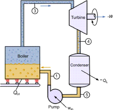
Figure 1.12 Diagram to show the Rankine Cycle and example of combust (Muller-Steinhagen, 2011).
How Does a Pyrolysis Biomass System Work?
Fast Pyrolysis is used in the PyrEng biomass system. Fast pyrolysis involves the thermal decomposition of carbon-based material in this case biomass in the absence of oxygen at low pressure and around 500oC. This results in the biomass being vaporized leaving a residue of char and ash. This fast pyrolysis in the PyrEng system produces bio oil as an intermediary liquid which can be compressed and ignited as it is an energy-dense liquid feedstock that can be utilized within a compression engine and used as a fuel to produce electricity (A.V. Bridgwater, 2002).
How Is Bio-Oil Created?
The bio-oil is created by first drying the feedstock making sure most of the moisture is released. It is then heated to further release moisture and some gas and char. This is done around 100 – 300oC. The biomass is then cooled to form ash, char, permanent gases and the desired bio-oil intermediary liquid. The remaining vapours are further vaporized at a temperature above 600oC to become secondary char and more permanent gases.
Bio-Oil Disadvantages
However, bio-oil if stored for too long can start to separate out into different phases. Moreover, it can become increasingly thick leading to complications in use as a fuel for compression engines. To combat the separation bio-oil must be kept in storage conditions with less than 30% water content to stop the bio-oil mixture from separating from an aqueous phase and a gummy-like phase as seen in figure 1.13. Furthermore, bio-oil can age leading to a change in properties reducing usability. To protect against ageing, it is important to keep low temperatures and reduce sheer stress and both can lead to accelerated ageing. This leads to storage, handling and transportation differences compared to other biomass systems.
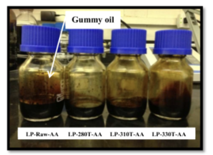
Figure 1.13 liquid oil phase (left) and gummy oil phase (right) of bio-oil after 9 months storage leading to complete phase separation (Jiajia Meng, 2015).
Bio-oil can be treated and co-fed into existing fossil fuel systems such as crude oil refineries. This means it can be used to curb the heavy reliance on crude oil. This is done by deoxygenating the bio-oil to create a more hydrocarbon like substance with low oxygen composition.
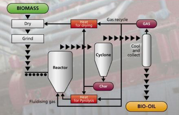
Figure 1.14 Diagram to show the process of converting biomass into bio-oil via fast pyrolysis in the PyrEng biomass system (Zafar, 2018).
GasEng is a form of atmospheric gasification whereby biomass is converted into syngas as well as tar and ash. These products are the cleaned via a gas clean-up where pure syngas is retained as an intermediate process gas, ash and tar are removed.
Particulates can be removed by the action of a few techniques such as filters, wet scrubbers and cyclones. Tar is any component with a molecular weight of 78 or higher. They are primary or secondary organic compounds. Tar is made up of mostly aromatic hydrocarbon which condense within engines and can cause tar build-up and deposits damaging components and reducing efficiency. The Tar is removed by primary or secondary tar removal.
Primary Tar removal is done in-situ via changing gasification operating and design conditions to reduce tar production and by adding catalysts as well as using different fluidised bed materials to convert tar into other products.
Secondary tar removal is when tar is reduced. This can be done by physically cleaning the tar by condensing tar and using scrubber/ filters. Another form of secondary tar removal is by cracking. Cracking is done by converting the tar into smaller molecules such as H2 or CO e.g. within modern cars with a catalytic converter. Once the Tar and particulates are removed, the gas is cleaned and sent to a spark engine where it can be combusted to form energy and electricity.
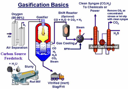
Figure 1.15 Diagram to show the process of converting biomass into syngas via the gasification method within the GasEng biomass system (Waste 2 Energy World, 2019).
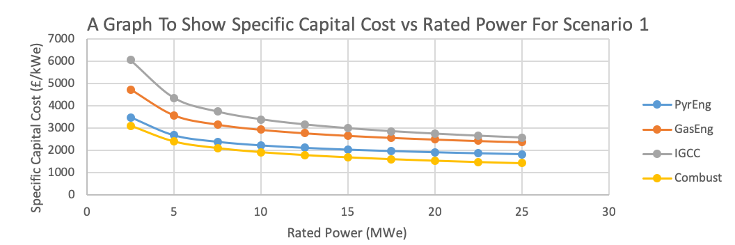
Graph 1.12 Graph to show specific capital costs compared to rated power for Scenario 1, Feed cost £30 per oven-dry tonne and 0% Learning Factor.
Graph 1.12 shows that IGCC has the highest specific capital costs over every rated power over the range out of the 4 different biomass systems. Starting at £6043.35k at 2.5MWe and ending at 25MWe with a specific capital cost of £3551.23k. Compared to the prices of the others such as GasEng at 2.5MWe has a specific capital cost of £4708.00k lowering to £2357.91k at 25MWe, PyrEng at 2.5MWe with a specific capital cost of £3467.02k lowering to £1814.19k at 25MWe and finally combust with a specific capital cost of £3089.43k at 2.5MWe lowering to £1412.36k at 25MWe.
IGCC is relatively new so the technology required to start and produce IGCC biomass systems is more expensive than old systems that have been mass-produced and in circulation for many years, allowing for second-hand systems to become cheaper adhering to the basic economic principles of supply and demand. The lower the supply, the scarcer and therefore the higher the cost for specialist equipment as it does not utilize economies of scale.
Moreover, as you can see in Table 1.11 the conversion costs for IGCC at £7170k are much higher than the other 3 biomass systems with PyrEng having £3460k, GasEng at £5220k and Combust having £1930k. This is down to the increased equipment required for IGCC compared to other biomass systems. The majority of the increased cost can be attributed to the gas clean up section of the IGCC method as this requires more equipment in the middle of the conversion process than other methods which do not have a complex gas clean up section involved.

Table 1.11 Table to show the Current Capital costs for IGCC.

Table 1.12 Table to show the Current Capital costs for GasEng.
The second highest specific capital cost over every rated power range is GasEng with a conversion cost of £5220k as seen in Table 1.12. This is similar to IGCC as they are both forms of gasification. Gasification again has higher specific capital costs compared to pyrolysis and complete combustion due to the higher number of specific capital equipment involved in the conversion of biomass feed to electricity through the formation of syngas. This is because to retrieve pure syngas, equipment such as carbon capture, scrubbers and filters are required to remove impurities and other undesirable products.
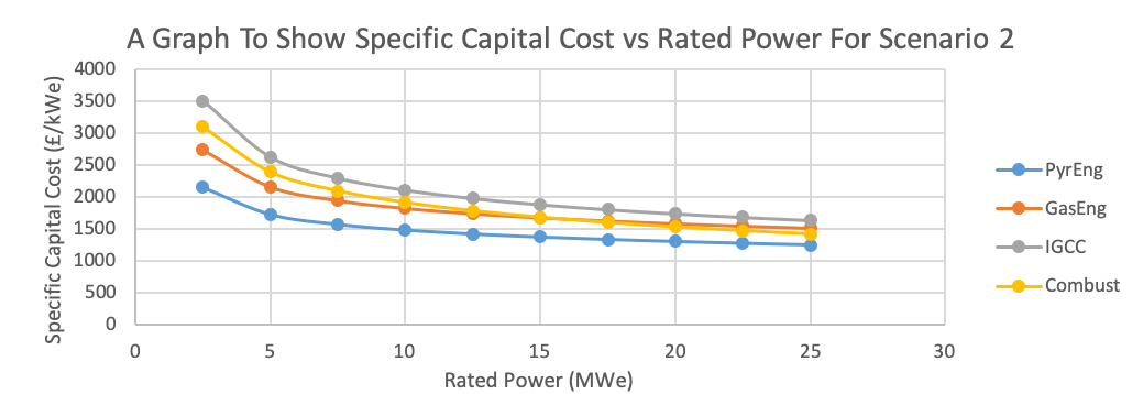
Graph 1.13 Graph to show the specific capital cost compared to rated power for scenario 2, £30 feed cost per oven-dry tonne and 20% learning factor.
The Learning factor can be described as acquiring new knowledge and information about specific processes. In this case, as time passes more innovation and technological advances occur therefore, increasing the efficiencies of equipment and reducing the cost allowing for equipment to age, lower production costs as well as a growing second hand market allowing for cheaper prices.
Graph 1.13 shows that the IGCC has the highest specific capital cost over the whole rated power range as stated before due to the higher capital costs involved in purchasing the capital equipment required in the conversion process due to the gas clean up section. For example, at 2.5MWe the IGCC has a specific capital cost of £3500.56k, combust is £3089.43k, GasEng is £2728.26k and finally PyrEng is £2148.10k compare this to the end of the rated power range at 25MWe the IGCC stays the highest at £1633.41k, the GasEng increases to the second highest specific capital cost with £1506.52k with combust just below with £1412.36k and PyrEng stays with the lowest specific capital cost at £1245.64k.
There is no change in the combust compared to graph 1.12 as combust is mature therefore, no learning factor as it is old and well developed with large amounts of accessible data. Moreover, due to its reliance on unsustainable energy sources and less clean nature compared to other biomass systems there is no need or desire to increase the innovation within combust biomass systems.
GasEng starts with a lower specific capital cost than combust at £2728.26k. However, this increases making the specific capital cost higher than that of combust at around 15MWe meaning by the end of the rated power range GasEng has a higher specific capital cost of £1506.52k compared to that of combust at £1412.36k.
PyrEng has the lowest specific capital cost compared to the other biomass systems as there is greater learning in areas such as preparation as seen in table 1.13. This is because there is greater interest and large scale developments are being carried out on pyrolysis with the use of diesel engines as compared to the use of gas turbine using fast pyrolysis (A.V. Bridgwater, 2002).
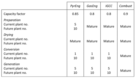
Table 1.13 Table to show learning factors for each biomass system in each different capital cost sections.
Scenario 3, £50 feed cost per oven-dry tonne and 20% learning factor as well as Scenario 4, £10 feed cost per oven-dry tonne and 20% learning factor also had graphs produced. However, these graphs are identical to graph 1.13 due to no learning factor difference which directly affects the specific capital costs, rather, the feed cost changes. Feed cost is an element of operating costs and not capital costs therefore; it does not affect the graphs comparing specific capital costs to rated power as it does not contribute to either.
Moreover, PyrEng is the only biomass system that has not got a mature preparation stage. This is because PyrEng preparation of biomass feed must be done with very high temperatures of above 1000oCs-1 with a low feed moisture content of 10% or less and a particle size of 1-2mm unlike the 3 other biomass systems which use conventional feed preparation. For example, the use of an updraft gasifier in the gasification processes involved in IGCC and GasEng can tolerate a feed with a much higher moisture content with as much as 50% MC of feed without the need to have a separate drying like in PyrEng. Moreover, a larger particle size can also be used of around 10-100mm as compared to 1-2mm of PyrEng.
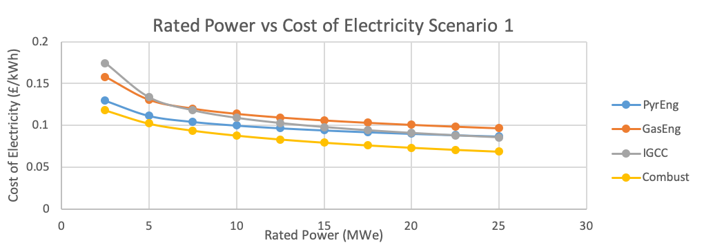
Graph 1.14 Graph to show the cost of electricity compared to rated power for Scenario 1, Feed cost £30 per oven-dry tonne and 0% Learning Factor.
Graph 1.14 shows that the cost of electricity at 2.5MWe at the beginning of the rated power range is cheapest for combust with a price of £0.12kWh and most expensive for IGCC at £0.18kWh. This Can be attributed to the higher number of capital equipment required in the IGCC process in the forms of gas clean-up. By the end of the rated power range GasEng has the highest price of electricity with £0.10kWh with the lowest being Combust again with a price of £0.07kWh. PyrEng overtakes IGCC by 20MWe for the second most expensive for cost of electricity.
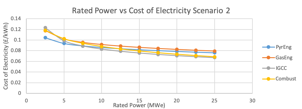
Graph 1.15 Graph to show the cost of electricity compared to rated power for Scenario 2, Feed cost £30 per oven-dry tonne and 20% Learning Factor.
Graph 1.15 shows that the cost of electricity at 2.5MWe at the beginning of the rated power range is cheapest for PyrEng with a price of £0.10kWh and most expensive for IGCC at £0.12kWh. By the end of the rated power range GasEng has the highest price of electricity with £0.08kWh with the lowest being IGCC with a price of £0.07kWh. PyrEng overtakes Combust by 12.5MWe for the second most expensive for cost of electricity.
Graph 1.16 shows that the cost of electricity at 2.5MWe at the beginning of the rated power range is cheapest for PyrEng with a price of £0.12kWh and most expensive for Combust at £0.14kWh. By the end of the rated power range GasEng has the highest price of electricity with £0.09kWh with the lowest being IGCC with a price of £0.08kWh. PyrEng overtakes Combust by 15MWe for the second most expensive for cost of electricity.
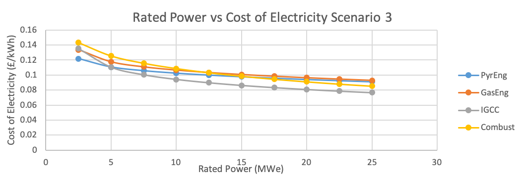
Graph 1.16 Graph to show the cost of electricity compared to rated power for Scenario 3, Feed cost £50 per oven-dry tonne and 20% Learning Factor.
Graph 1.17 shows that the cost of electricity at 2.5MWe at the beginning of the rated power range is cheapest for PyrEng with a price of £0.09kWh and most expensive for IGCC at £0.11kWh. By the end of the rated power range GasEng has the highest price of electricity with £0.07kWh with the lowest being combust with a price of £0.05kWh. PyrEng overtakes Combust by 17.5MWe for the second most expensive for cost of electricity.
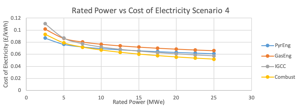
Graph 1.17 Graph to show the cost of electricity compared to rated power for Scenario 4, Feed cost £10 per oven-dry tonne and 20% Learning Factor.
The utility cost for IGCC is the highest at £54.7k y-1 compared to £36.9k y-1 for PyrEng, £49.3k y-1 for GasEng and -£27.2k y-1. This can be attributed to the greater number of equipment required for gasification processes that are within IGCC and GasEng thus costing more in utilities. Furthermore, the labour cost is also higher in IGCC at £651 man days y-1 compared to £423 man days y-1 for the other 3 biomass systems. This could be due to the pressurized system involved in the IGCC process leading to greater control and safety precautions requiring a greater number of operators and more staff for safety on site. Maintenance is also highest for IGCC with £105.0k y-1 compared to -£11.1k y-1 combust, £22.1k y-1 for PyrEng and £53.6k y-1 for GasEng. Again this can be attributed to the higher number of equipment required for gasification process involved in GasEng and IGCC.
For the operating costs, feed transport stays consistent due to the same method used across all 4 biomass systems. Another factor as to why there is a difference in operating and capital costs can be attributed to the different types of reactors used for each biomass system.
What Is A Moving Grate System?
Within Moving grate systems, the biomass is fed onto the moving grate via gravity. The biomass is then dried initially as the moving grate bed moves after which it is ignited, burned and cooled whereby the ash is removed. The moving grate operating temperatures are around 800-1000oc (European Biomass Industry Association, 2019).

Figure 1.16 Diagram to show a moving grate combustor (European Biomass Industry Association, 2019)
There are two types of fluidised bed reactors, a moving fluidised bed reactor and a fixed fluidised bed reactor. Fluidised bed reactors burn biomass material within a hot bed of granular material for example, sand which is kept hot by a primary air feed keeping it molten with a second air stream above to achieve complete combustion. Fluidised beds operate at around 750-950oC.
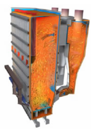
Figure 1.17 Diagram to show a circulating fluidised bed (moving fluidised bed) (European Biomass Industry Association, 2019)
Due to the increased compactness of the fluidised bed reactor compared to the moving grate combustor coupled with less use of excess air with around 40% compared to an excess air amount of 80-90% for moving grate, the fluidised bed has a lower capital and operating cost. Moreover, a more efficient burning leads to a lower bottom ash amount of 16% compared to 22% for moving grate meaning that it requires less maintenance, produces cleaner products therefore, less cleaning required after the process (Morin, 2014).
Pyrolysis has a cheaper utility cost than the gasification process with £35.9k y-1 as compared to the gasification processes with IGCC having a utility cost of £54.7k y-1and GasEng with a utilities cost of £49.3k y-1 due to the fact pyrolysis utilizes gas recycling unlike the gasification process.
Many assumptions were made during the calculation for example 50% wet basis which when analysed against the biomass systems is much higher than required for IGCC and GasEng and much less than pyrolysis within PyrEng.
Alternative Sources of Energy Production Analysis
There are many alternatives sources of energy like renewable sources such as solar, wind and thermal amongst others. Moreover, comparisons can also be made with conventional sources of energy such as coal and natural gas. For example in the year 2007 49% of total US power generation was via the use of coal as an energy source followed by natural gas at 21% (Kaplan, 2008). This is mainly due to the cheap nature of coal feed coupled with the greater energy production involved in the burning of coal as shown with the published values. Values online state that compared to a natural gas combined cycle power plant as a base rate, IGCC is 34% more expensive (Kaplan, 2008). Moreover, using natural gas with an energy density of 23,00 MJ m-3 as compared to 30% moisture content wood chip with an energy density of 3,100MJ m-3 (Forest Research, 2019) shows that there is a long way for IGCC and biomass methods to progress until it is a viable mass scale option to replace the use of non-renewable fossil fuel methods such as natural gas.
Renewable methods such as solar and wind are also viable alternatives with both having free sources of energy. However, they are intermittent sources of energy and rely heavily on uncontrollable conditions such as degree of sunshine and level of wind respectively. In 2014 over a seven-day period in Arizona with variable cloud coverage, solar energy only managed an average of 25% of rated power output. Moreover, the combined total of all wind turbines contributing to the UK national grid only managed 32.5% average output over a 1 month period also showing major fluctuations in power (VIASPACE, 2019).
Nuclear is also an alternative and popular source of energy. It is cheaper than IGCC in scenario 4 with the cheapest feed cost and learning factor of 20% which achieved an electricity cost price of £0.11 kWh compared to nuclear which has a electricity cost price of £0.09 kWh (DeRosa, 2015). However, nuclear energy has greater build time compared to other energy sources as well as having greater complexity, initial cost price and although they do not produce greenhouse gases there is a compromise due to its highly radioactive nature.
Conclusion
In conclusion, IGCC is seen as the most viable long term Biomass system of the four systems reviewed in this report. It has the cheapest electricity cost at the lowest feed cost other than combust and also due to the gas clean-up section can be seen to be the most environmentally friendly of the biomass systems discussed. However, research and development must carry on in order for IGCC to be a substitute for conventional fossil fuel methods such as natural gas and coal.
Biomass is a growing industry and more research and development is continuously taking place with many more project scheduled to be commissioned and designed in the future. However, more incentives must be introduced to allow private companies to invest more time and effort into biomass for it to be a serious long term and mass scale alternative to conventional energy producing methods. For this to occur key issues must be made aware to the public through education so that social movements and a growing pressure can lead to change especially in emerging economies such as china and India. Furthermore, government regulation, legislations and taxing as well as potential subsidies could also provide more incentives for private companies to invest in long term mass based research and development studies. Steps taken such as the Paris agreement where emerging economies are being made aware of the damage their growth and increased energy requirement is causing are steps in the right direction and it is tantamount that initiatives like these carry on.
References
A.V. Bridgwater, A. T. (2002). A techno-economic comparison of power production by biomass fast pyrolysis with gasification and combustion. Elsevier.
ATech Electronics. (2019). Biomass combustion. Retrieved from Fumis: http://www.fumis.si/en/about-biomass-combustion
Basu, P. (2010). Biomass Gasification and Pyrolysis. Amsterdam: Elsevier.
DeRosa, T. (2015). Renewables vs. Nuclear: Do We Need More Nuclear Power? Retrieved from Renewable Energy Wolrd: https://www.renewableenergyworld.com/ugc/articles/2015/04/renewables-vs-nuclear-do-we-need-more-nuclear-power.html
ecoprog. (2019). Biomass to Power 2018/2019. Retrieved from ecoprog: https://www.ecoprog.com/publications/energy-management/biomass-to-power.htm
European Biomass Industry Association. (2019). Medium to large scale combustors. Retrieved from eubia: http://www.eubia.org/cms/wiki-biomass/combustion/medium-to-large-scale-combusters/?fbclid=IwAR3F3mR_k1UJB1t5XeXIINadEjwygSZHZ02O2dqKvSkx6163zAM5g5w-OiM
Forest Research. (2019). Typical calorific values of fuels. Retrieved from Forest Research: https://www.forestresearch.gov.uk/tools-and-resources/biomass-energy-resources/reference-biomass/facts-figures/typical-calorific-values-of-fuels/
Jiajia Meng, A. M. (2015). Thermal and Storage Stability of Bio-Oil from Pyrolysis of TorrefiedWood. Raleigh, North Carolina: Energy&Fuels.
Kaplan, S. (2008). Power Plants: Characteristics and Costs. Washington: Congerssional Research Service.
Mitsubishi Hitachi Power Systems . (2019). Integrated Coal Gasification Combined Cycle (IGCC) Power Plants. Retrieved from MHPS: https://www.mhps.com/products/igcc/
Morin, O. (2014). Technical and Environmental Comparison of Circulating Fluidized Bed (CFB) and Moving Grate Reactors. Columbia: Columbia University.
Muller-Steinhagen, H. M. (2011, February 7). RANKINE CYCLE. Retrieved from Thermopedia: http://www.thermopedia.com/content/1072/rankinecycle
R K BAGUL, D. S. (2013). Entrainment phenomenon in gas–liquid two-phase flow: A review. Mumbai: Indian Academy of Sciences.
VIASPACE. (2019). Biomass Compared to Fossil Fuels, Solar and Wind. Retrieved from VIASPACE: http://www.viaspace.com/biomass_versus_alternatives.php
Wang, T. (2016). Integrated Gasification Combined Cycle (IGCC) Technologies. Amsterdam: Elsevier.
Waste 2 Energy World. (2019). GASIFICATION. Retrieved from Waste 2 Energy World: http://www.waste2energyworld.com/gasification.htm
Zafar, S. (2018, December 29). Biomass Pyrolysis Process. Retrieved from BioEnergy Consultant : https://www.bioenergyconsult.com/tag/uses-of-bio-oil/

Hassan graduated with a Master’s degree in Chemical Engineering from the University of Chester (UK). He currently works as a design engineering consultant for one of the largest engineering firms in the world along with being an associate member of the Institute of Chemical Engineers (IChemE).

