The use of Fe-based chemical looping is an improved and updated version of the steam iron process and could be also considered for NH3 production. Chemical looping uses solid intermediates in a reaction-regeneration cycle to decompose one reaction into two or more sub reactions. Chemical looping removes the pathways of any inert or undesired substance having direct contact with the desired species, producing a pure product stream [1]. Chemical looping provides a means with the conversion of carbonaceous fuels into selected products such as hydrogen, electricity and provides carbon capture. You can read more about FE Based Chemical Looping here:
Zaidi, A., de Leeuwe, C., Chansai, S., Hardacre, C., Garforth, A., Parlett, C., & Spallina, V. (2025). Development of iron-nickel containing perovskites with increased oxygen carrier capacity for chemical looping H2 production. Journal of Environmental Chemical Engineering, 13(1), 115069. https://doi.org/10.1016/j.jece.2024.115069
One of the earliest reference to chemical looping combustion is Lewis and Gilliland, in 1954, publishing ‘Production of Pure CO2‘ (patent US2665972A), which described a concept like chemical looping combustion, as well the idea of using oxygen carriers to reduce fuels [2]. In the 1980s Richter and Knoche proposed the principle of chemical looping combustion (CLC) to improve fossil fuel power plants [3].
The name CLC was first used by Ishida in the 1980s in a study to reduce exergy losses in natural gas power plants when converting fuel energy into thermal energy [4]. In 1994 Ishida and Jin continued research for the integration of CLC in power plants. They developed a new system for power generation to reduce the exergy destruction caused by combustion and heat exchange and solve the environmental issues associated with CO2 by recovering and utilising it [5].
In the early 2000s, CLC hadn’t been demonstrated on a large plant scale with only a handful of test cycle runs, with the small number of oxygen carries being investigated [6].
The EU funded CO2 capture program provided the first notable trial for CLC [7], with the experiment used more than 300 different types of oxygen carriers [8]. Another EU project was the ‘CO2 Capture and Hydrogen Production from Gaseous Fuels’ (CACHET). This project focused on the different applications for hydrogen production and carbon capture and the integration of chemical lopping in auto-thermal reforming and steam reforming [9].
With the increased funding and attention that chemical looping was receiving, Chalmers university successfully operated a unit for over 1000 hours [10], successfully testing a large CLR unit under conditions like those seen in industry [11]. Feasibility study and simulation was done on a 3 MWe unit [12] and large scale testing demonstrations was done on 455 MWe commercial unit [13], [14], [15].
By 2010 chemical looping processes had achieved more than 3500 hours of continuous operation and a significant number of papers, and patents in the space of 10 years, with testing of 36 different oxygen carrier materials [16].
Chemical Looping In a Packed Bed
A packed bed chemical looping reactor consists of the oxygen carrier particles packed into the reactor with alternating gas feed to the reactor (Figure 1.4). Noorman et al. [17] showed the feasibility of chemical looping using a packed bed reactor, shifting from the fluidised bed and bubbling bed reactors used for chemical looping previously [18].
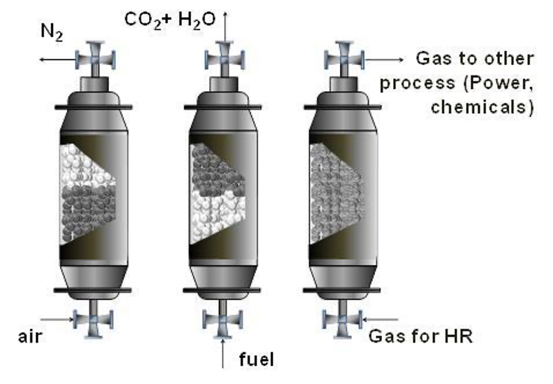
Chemical looping performed in a packed bed reactor conventionally has three stages. The first stage is oxidation in air, producing hot oxygen-depleted air (N2), which is used for power generation by being fed to a turbine. The next stage is where the oxidised oxygen carrier is reduced using a low-grade fuel, producing CO2 and H2O we can be easily separated for CO2 sequestration. The third stage involves a heat removal stage, but this is dependent on the oxygen carrier being used [19], [20].
The benefit of using a packed bed reactor compared to using a fluidised bed is the difficulty associated with the separation of gases and particles is avoided and full utilisation of oxygen carrier oxidation states [17].
The flexibility of the types of chemical looping process in a packed bed reactor has been demonstrated with dry, wet and steam reforming compositions with the process having a dependence on the oxygen carrier used, with high material stability and reactivity being required [20].
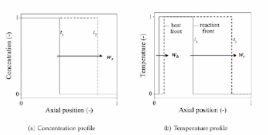
When operating a PBR for chemical looping, two different velocities must be taken into account; these are the heat front and reaction front (Figure 1.5). The heat front involves the thermal motion of particles, with a velocity slower than the reaction front, with heat transfer occurring when the oxygen carrier is cooled down to the gas inlet temperature. The reaction front is the thin area between separating the hot products from the cool reactants that determines the gas-solid conversion and the heat generated in the bed [19], [21].
When significant flow rates go through the reactor, the heat front velocity is greater than the reaction front velocity. The initial solid temperature isn’t affected by the maximum reactor temperature [21].
Chemical Looping Reforming
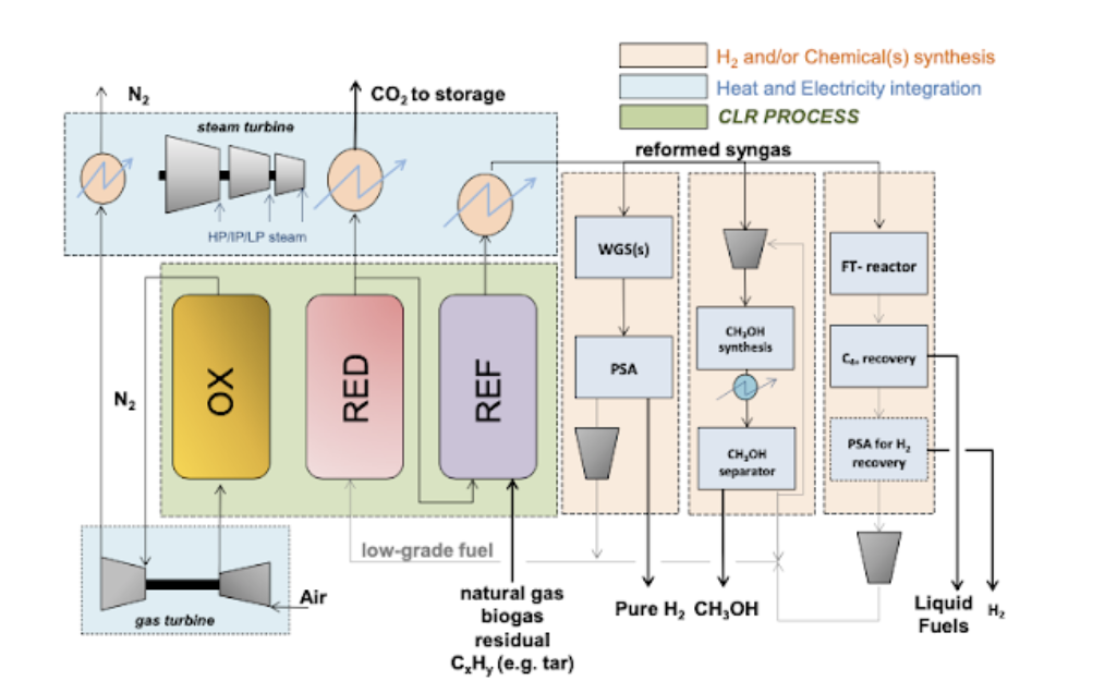
Recently, there has been a widening of this focus onto hydrogen production and other chemicals using chemical looping reforming (Figure 1.6) due to its ability of inherent separation producing a pure product coupled with carbon capture [22]. This is the case of syngas for methanol, ammonia and also liquid fuels.
Mattisson et al. [23] first proposed chemical looping reforming (CLR) in 2001. CLR utilises the same basic principles as CLC, with the difference being the partial oxidation of hydrocarbon fuel to form reformate syngas. H2O is used to increase the H2/CO ratio desired for a process like Fischer Tropsch, which requires an H2/CO ratio of 2 [24].
The reformate syngas produced can be put through other processes to produce chemicals such as; H2, CH3OH, NH3, Fischer Tropsch processes. There are variations of CLR depending on the desired; these include steam reforming integrated with chemical looping combustion (SR-CLC), autothermal chemical looping reforming (CLR-A) and chemical looping steam methane reforming (CL-SMR).
Steam reforming integrated with chemical looping combustion
SR-CLC is a syngas generation process that Rydén and Lyngfelt [25] proposed. SR-CLC involves the conversion of steam and hydrocarbons, which is the same as conventional steam reforming. The CLC element is there to provide a source of heat for the endothermic reactions [16].
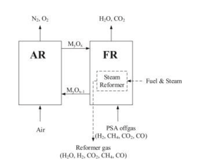
The reactor configuration used in SR-CLC consists of an air reactor for oxidation of the oxygen carrier and a fuel reactor to reduce the oxygen carrier using a fuel. The reforming stages consist of a series of tubes operated at elevated pressures and packed with the oxygen carrier. The reforming tubs are immersed within the fuel reactor (Figure 1.7), and during the reduction with the hot oxygen carrier, heat is transferred to the tubes for the reforming to occur [26], [27].
The position of the reforming tubes is due to the favourable conditions for heat transfer, with the hot particles easily maintaining a good tube wall temperature profile [16], [25]. Furthermore, favourable heat-transfer conditions have improved H2 selectivity compared to conventional SMR [25].
Producing pure H2 from SR-CLC requires integrating Water-Gas Shift (WGS) and Pressure Swing Adsorption (PSA), providing 100% carbon capture, which involves separating H2O from CO2, which is a simple process compared to the costly and energy-intensive carbon capture used in conventional SMR.
Issues present with SR-CLC are due to the possible degradation of the reforming tubes due to high temperatures, leading to cracks forming and loss of containment of the oxygen carrier into the air or fuel reactor [27]. Furthermore, the costs increase due to the requirement of WGS and PSA units, H2 production. Reduction of these costs would be necessary to generate H2 at a competitive price point. Otherwise, SR-CLC would be a better syngas production process.
Chemical looping autothermal reforming
H2 generation using CLR-A requires WGS and PSA units to maximise H2 from the syngas. CLR-A produces H2 without an external heat supply, removing the CO2 emissions caused by external combustion for heat supply [26]. The significant advantage of CLR-A is that the heat needed to convert the hydrocarbon fuel into syngas doesn’t involve costly O2 production and without any mixing of air with carbon-based fuels [28] (Figure 1.8).
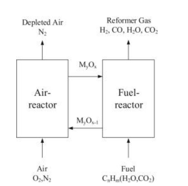
The heat balance is essential for CLR-A, with the heat generated from the exothermic oxidation of the oxygen carrier using air having to be sufficient enough to satisfy the heat required for the endothermic reduction and reforming stages [26], [28].
Other advantages of CLR-A are; less H2O and oxygen carrier are required per unit fuel feed, no NOX formation and produces syngas that can be used in methanol production and Fischer Tropsch, that isn’t possible with steam reforming of CH4 and reduced sulphur poisoning of oxygen carrier [29], [30].
Chemical looping steam methane reforming
CL-SMR is a process that produces pure H2 and syngas separately. Like other forms of chemical looping, the oxygen carrier is partially reduced by methane in the fuel reactor producing syngas. The next step is the difference with steam being used to oxidise the oxygen carrier to produce pure H2. An air reactor is sometimes included to recover the oxygen carrier due to steam not fully recovering the lattice oxygen entirely as it is a weak oxidising agent (Figure 1.9) [28].

CL-SMR is an attractive option due to the possibilities of producing H2 and syngas without the need for WGS or PSA units which reduces costs. The oxygen carrier must show high levels of reactivity with both CH4 and H2O throughout many cycles and must be resistant to carbon deposition, which can reduce the materials performance and carbon particles reacting the H2O leading to contamination of the H2 produced. The current literature is looking at ways to optimise the performance of oxygen carriers (Fe-based, Ni-based, Cu-based etc.) to find a suitable material to be used in CL-SMR [31]. The case (a) is not thermally balanced while case (b) it is because the presence of air is providing heat to the system.
References
- [1] A. Tong, M. V. Kathe, D. Wang, and L.-S. Fan, Handbook of Chemical Looping Technology. 2017. doi: 10.1002/9783527809332.
- [2] K. W. Lewis and E. R. Gilliland, ‘Production of pure carbon dioxide’, 1954
- [3] H. J. Richter and K. F. Knoche, ‘Reversibility of Combustion Processes’, in Efficiency and Costing, 1983. doi: 10.1021/bk-1983-0235.ch003.
- [4] M. Ishida, D. Zheng, and T. Akehata, ‘Evaluation of a chemical-looping-combustion power-generation system by graphic exergy analysis’, Energy, vol. 12, no. 2, 1987, doi: 10.1016/0360-5442(87)90119-8.
- [5] M. Ishida and H. Jin, ‘A new advanced power-generation system using chemical-looping combustion’, Energy, vol. 19, no. 4, 1994, doi: 10.1016/0360-5442(94)90120-1.
- [6] S. Abuelgasim, W. Wang, and A. Abdalazeez, ‘A brief review for chemical looping combustion as a promising CO2 capture technology: Fundamentals and progress’, Science of The Total Environment, vol. 764, Apr. 2021, doi: 10.1016/j.scitotenv.2020.142892.
- [7] A. Lyngfelt, B. Kronberger, J. Adanez, J. X. Morin, and P. Hurst, ‘The grace project: Development of oxygen carrier particles for chemical-looping combustion. Design and operation of a 10 kW chemical-looping combustor’, in Greenhouse Gas Control Technologies, 2005. doi: 10.1016/B978-008044704-9/50013-6.
- [8] J. X. Morin and C. Béal, ‘Chemical Looping Combustion of Refinery Fuel Gas with CO2 Capture’, in Carbon Dioxide Capture for Storage in Deep Geologic Formations, 2005. doi: 10.1016/B978-008044570-0/50123-9.
- [9] M. Rydén et al., ‘Developing chemical-looping steam reforming and chemical-looping autothermal reforming’, in Carbon Dioxide Capture for Storage in Deep Geologic Formations – Results from the CO2 Capture Project, First Edit., vol. 3, Cplpress, 2009, ch. 14, pp. 181–200.
- [10] C. Linderholm et al., Chemical looping combustion with natural gas using spray-dried NiO-based oxygen carriers, vol. 3. 2009.
- [11] M. Rydén et al., ‘Developing chemical-looping steam reforming and chemical-looping autothermal reforming’, in Carbon Dioxide Capture for Storage in Deep Geologic Formations – Results from the CO2 Capture Project, First Edit., vol. 3, Cplpress, 2009, ch. 14, pp. 181–200.
- [12] N. Berguerand and A. Lyngfelt, ‘The use of petroleum coke as fuel in a 10 kWth chemical-looping combustor’, International Journal of Greenhouse Gas Control, vol. 2, no. 2, 2008, doi: 10.1016/j.ijggc.2007.12.004.
- [13] C. Béal et al., ‘Development of Metal Oxides Chemical Looping Process for Coal-Fired Power Plants’, Darmstadt: 2nd International Conference on Chemical Looping, Sep. 2012.
- [14] L. Zeng et al., ‘Coal Direct Chemical Looping Retrofit to Pulverized Coal Power Plants for In-Situ CO2 Capture’, Columbus, 2013.
- [15] H. E. Andrus, Jr., J. H. Chiu, C. D. Edberg, P. R. Thibeault, and D. G. Turek, ‘Alstom’s Chemical Looping Combustion Prototype for CO2 Capture from Existing Pulverized Coal-Fired Power Plants’, Pittsburgh, PA, and Morgantown, WV (United States), Sep. 2012. doi: 10.2172/1113766.
- [16] J. Adanez, A. Abad, F. Garcia-Labiano, P. Gayan, and L. F. De Diego, ‘Progress in chemical-looping combustion and reforming technologies’, 2012. doi: 10.1016/j.pecs.2011.09.001.
- [17] S. Noorman, M. van Sint Annaland, and Kuipers, ‘Packed Bed Reactor Technology for Chemical-Looping Combustion’, Industrial & Engineering Chemistry Research, vol. 46, no. 12, Jun. 2007, doi: 10.1021/ie061178i.
- [18] R. Ocone, ‘Transport phenomena in packed bed reactor technology for chemical looping combustion’, Chemical Engineering Research and Design, vol. 90, no. 10, Oct. 2012, doi: 10.1016/j.cherd.2012.02.012.
- [19] V. Spallina, F. Gallucci, and M. van Sint Annaland, ‘Chemical Looping Processes Using Packed Bed Reactors’, in Handbook of Chemical Looping Technology, 2018. doi: 10.1002/9783527809332.ch3.
- [20] V. Spallina, B. Marinello, F. Gallucci, M. C. Romano, and M. Van Sint Annaland, ‘Chemical looping reforming in packed-bed reactors: Modelling, experimental validation and large-scale reactor design’, Fuel Processing Technology, vol. 156, 2017, doi: 10.1016/j.fuproc.2016.10.014.
- [21] R. Gort and J. J. H. Brouwers, ‘Theoretical analysis of the propagation of a reaction front in a packed bed’, Combustion and Flame, vol. 124, no. 1–2, 2001, doi: 10.1016/S0010-2180(00)00149-8.
- [22] X. Zhu, Q. Imtiaz, F. Donat, C. R. Müller, and F. Li, ‘Chemical looping beyond combustion-a perspective’, 2020. doi: 10.1039/c9ee03793d.
- [23] T. Mattisson and A. Lyngfelt, ‘Applications of chemical-looping combustion with capture of CO2’, in Second nordic minisymposium on carbon dioxide capture and storage, 2001.
- [24] C. Allevi and G. Collodi, ‘Hydrogen production in IGCC systems’, in Integrated Gasification Combined Cycle (IGCC) Technologies, Elsevier, 2017. doi: 10.1016/B978-0-08-100167-7.00012-3.
- [25] M. Rydén and Lyngfelt. A, ‘Using steam reforming to produce hydrogen with carbon dioxide capture by chemical-looping combustion’, Int J Hydrogen Energy, vol. 31, no. 10, Aug. 2006, doi: 10.1016/j.ijhydene.2005.12.003.
- [26] M. Luo et al., ‘Review of hydrogen production using chemical-looping technology’, 2018. doi: 10.1016/j.rser.2017.07.007.
- [27] M. R. Rahimpour, M. Hesami, M. Saidi, A. Jahanmiri, M. Farniaei, and M. Abbasi, ‘Methane Steam Reforming Thermally Coupled with Fuel Combustion: Application of Chemical Looping Concept as a Novel Technology’, Energy & Fuels, vol. 27, no. 4, Apr. 2013, doi: 10.1021/ef400026k.
- [28] M. Ortiz, A. Abad, L. F. de Diego, P. Gayán, F. García-Labiano, and J. Adánez, ‘Optimization of a chemical-looping auto-thermal reforming system working with a Ni-based oxygen-carrier’, Energy Procedia, vol. 4, 2011, doi: 10.1016/j.egypro.2011.01.071.
- [29] H. RYU, G. JIN, and C. YI, ‘Demonstration of inherent CO2 separation and no NOx emission in a 50kW chemical-looping combustorContinuous reduction and oxidation experiment’, in Greenhouse Gas Control Technologies 7, Elsevier, 2005. doi: 10.1016/B978-008044704-9/50238-X.
- [30] F. García-Labiano, L. F. de Diego, P. Gayán, J. Adánez, A. Abad, and C. Dueso, ‘Effect of Fuel Gas Composition in Chemical-Looping Combustion with Ni-Based Oxygen Carriers. 1. Fate of Sulfur’, Ind Eng Chem Res, vol. 48, no. 5, Mar. 2009, doi: 10.1021/ie801332z.
- [31] M. H. S. Garai, M. R. Khosravi-Nikou, and A. Shariati, ‘Chemical Looping Steam Methane Reforming via Ni‐ferrite Supported on Cerium and Zirconium Oxides’, Chem Eng Technol, vol. 43, no. 9, Sep. 2020, doi: 10.1002/ceat.202000054.

Dr. Adam Zaidi, PhD, is a researcher at The University of Manchester (UK). His doctoral research focuses on reducing carbon dioxide emissions in hydrogen production processes. Adam’s expertise includes process scale-up and material development.’