Reactor Design
For reactor design, Fogler’s is a really good start for understanding the basics of reactor design and then books such as by Levenspiel are really useful once the basic knowledge has been acquired, but we will be focusing on Fogler’s algorithm for understanding of problems for reactor design that will be essential for exams and coursework’s.
With reactor design relatively simple theories and models help to give insight into what is going on inside the reactor and if any changes can be made to increase the performance, however, due to this simplicity making alterations to existing designs is a more preferred practice.
The shape of reactors can vary but they will resemble a tank or a tube for the most part and are either a batch reactor or a continuous reactor. Batch reactors have constant changing compositions and are simple to operate and aren’t steady-state, whilst continuous reactors can be two kinds PFR, Plug Flow reactor or CSTR, continuously stirred tank reactors which are used a lot in the industry due to their larger flow rates handling capabilities and control over product quality.
Batch Reactor
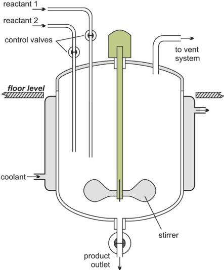
Batch reactor schematic diagram (The Essential Chemical Industry – online, 2013)
A batch reactor whilst the reaction is taking place has no flow into or out of the reactor, this is because during the reaction the batch reactor is a closed system. The reaction process in Batch reactors will produce a high conversion of the reactants however the disadvantage is the long reaction time which adds to costs such as labour costs as well as issues that are encountered in the industry such as unreliable batch qualities (Hafeez, 2019).
Plug Flow Reactor (PFR)
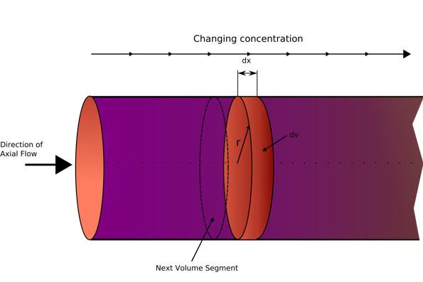
PFR schematic diagram (Wikipedia, 2020)
The plug flow reactor model, PFR (sometimes called continuous tubular reactor, CTR) is a cylindrical reactor with a tubular design. The type of flow going through the PFR is called plug flow, which is modelled as infinitely thin coherent plugs (see diagram above), that travels in an axial direction with each ‘plug’ being a different entity and is effectively a small batch reactor per each plug with each plug having a different composition from before or after it. the assumption that is made for a PFR is that the fluid will be perfectly mixed in the radial direction but not mixed at all in the axial direction. The residence time (total time spent in the reactor) is an impulse (a small narrow spike function), and is derived from the position of the fluid in the PFR, and is a key factor when scaling up flow reactors (Vapourtec, 2020).
Continuously Stirred Tank Reactors (CSTR)
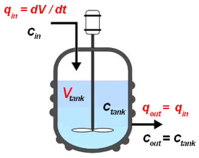
CSTR diagram (Wikipedia, 2020)
A continuous stirred tank reactor (CSTR) is a basically batch reactor with an impeller or other mixing device to provide efficient mixing. A CSTR is often referred to an idealised agitated vessel used to model operational variables used to attain specific outputs. Using a single CSTR leads to issue of sever back mixing, extremely poor residence time control which limit the performance of the CSTR and have a negative impact on product yield, selectivity and space-yield. Thus, to combat these issues CSTRs are used in cascades of 3 or 4 to promote better residence time control and reduce back mixing (Vapourtec, 2020).
Reactor Design – Equations
To be able to find out a design parameter for a reactor you require, and the first step required a mole balance (can be called Molecular mole balance) to find out from the established system boundary of the reactor on what mass; enters, leaves, stays in the reactor or is converted into a new species.
A material balance must be developed, which is simply:
Inlet Flow + Generation = Outlet Flow + Consumption + Accumulation
(1.11)
If the composition is uniform (the same at all points) in the reactor then the material balance can be done for the whole reactor, if it is not uniform then it needs to be done on an infinitesimal volume which needs to be integrated, this will become more clear when looking at batch and continuous reactors. Going forward there will be a range of notations used and making yourself familiar with these expressions is extremely important.
Ni – Number of moles of species ‘i’
Fi – Molar flow rate this is used for continuous reactors at a point in the system
Xi – Conversion of species ‘i’ during the chemical reaction
Ci – Concentration of species ‘i’ at a point during the chemical reaction
v – Volumetric flow rate
t – Time
Subscript ‘0’ – donates initial value when t = 0
Stoichiometry
For flow reactors:

(1.12)

(1.13)
For a batch reactor:

(1.14)

(1.15)
Conversion
Conversion refers to the number of moles of a species that has been changed or converted into a new species, for a batch reactor this will be in terms of moles and for a continuous flow reactor this will be in terms of molar flow rates, this is simply just a division of how much of species A has been used up over the original amount of species A at t = 0.

(1.16)

(1.17)
There is a special case when the densities are constant, or we assume constant density we then assume the volume is constant as (density = mass/volume) for the fluid element and conversion becomes:

(1.18)
Equation 1.18 can be further simplified due to the fact that CA/CA0 = 1 so

(1.19)
then this expression for conversion can be written as:

(1.20)
CAO will be constant and the XA and CA will be changing throughout the reaction. For liquids, when the density is constant volumetric flow rates are the same throughout:

(1.21)
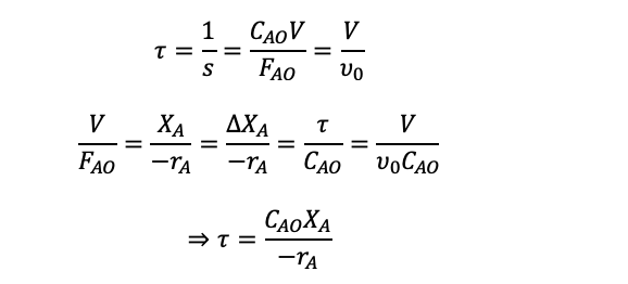
Space-Time and Space-Velocity
For a continuous flow reactor, space-time and space-velocity are used instead of reaction time which is used in batch reactors which represent the amount of time the reaction is going on for. Space-time (τ) is the time for the time taken for the one reactor volume of feed to go through the reactor and space-velocity (s) is how many reactor volumes of feed can be treated per unit of time.

(1.22)
Ideal Batch Reactor Mole Balance
Assuming the composition is the same throughout and is well-mixed (this helps in making the mass balance easier by eliminating terms), we can do a balance on the whole reactor volume, thus the mass balance becomes
0 = Consumption + Accumulation
(1.23)
Then stating that the consumption of species let’s call it A within the given volume:
Consumption of A is equal to:
-rAV←consumption is the reaction rate multiplied by the volume.
(1.24)
Thus the Accumulation of A is equal to:

(1.25)
This gives a mole balance of:

(1.26)
The reason for the differential is because we need to find out the conversion of species A over time.
Integrating gives and rearranging for t:
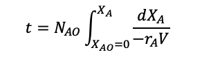
(1.27)
With a constant density and thus a constant volume:

(1.28)
(to make it easier a document will have all the final forms of the equations)
CSTR Mole Balance
CSTR Mass balance: Input = output + consumption
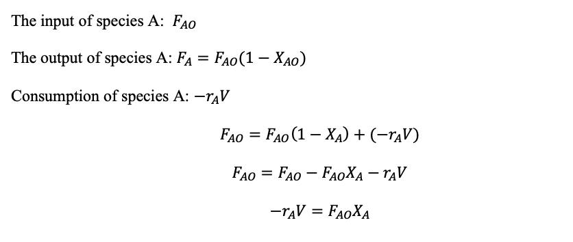
(1.29)
CSTR Performance Equation
The performance equation relates the reaction rate, volume, feed rate, and conversion of the species and we can rearrange the CSTR mole balance to get the performance equation and be able to work out the space-time or space velocity.
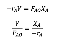
(1.29)
Then we can use the space-time equation seen previously:
PFR Performance Equation
Assuming constant density,

CAF – final concentration of species A
If the elementary reaction is given, we can easily form an expression for rA in terms of conversion and then integrate to find out the space-time.
To be able to solve the integral, Simpson’s rule will need to be used, and depending on your university lecturer you could be given the Simpson’s rule formula, but if not it isn’t too hard to learn and the best way to learn is to practice and try as many variations of questions at different levels of difficulty to get used to answering these equations which are usually heavily weighted in terms of marks.
The equation below is Simpsons 3rd rule this can usually be used most of the time unless stated otherwise.
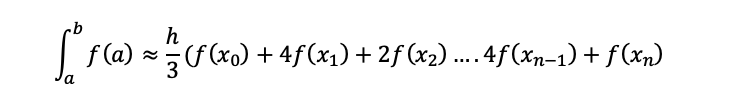
(1.35)
Changing Density
When the number of moles of gas, temperature or pressure changes then the density will no longer be constant, and we can then use the ideal gas law and then using the initial conditions and the final conditions inside the batch reactor and rationing them out:
Ideal gas law: pV =nRT
p – Pressure
V – Volume
n- Moles
R – Universal gas constant
T – Temperature
Initial conditions of gas:

Final conditions of gas: pV =nRT
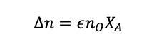
This is simply the initial number of moles plus the change in the total number of moles due to the reaction taking place.
Now we will introduce epsilon, which is the change in the number of moles of the limiting reactant after the reaction has taken place, divided by the original number of moles.
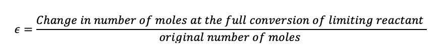
(1.39)
Then we can say, in a situation where species A is the limiting reagent
(1.40)
Remember, the total number of moles includes the leftover reactants that are in excess and any inert species that are present.
Using the change in moles formula, equation 1.37 into the volume equation 1.37:
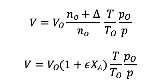
For a flow reactor, the volume is replaced with the volume flow rate:
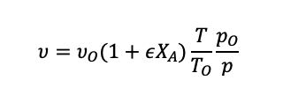
(1.41)
When the density is constant, we can assume that is equal to zero.
Example – limiting reagent
Air is comprised of roughly 21% oxygen, and the input feed to a reactor is 100 moles and sulphur dioxide is added as well and the input mixture is 28% sulphur dioxide and the remainder is air, the desired product is sulphur trioxide, what is the limiting reagent? and why?
2SO2 + O2 → 2SO3
References
The Essential Chemical Industry – online. (2013, March 18). Chemical reactors. Retrieved from The Essential Chemical Industry – online: https://www.essentialchemicalindustry.org/processes/chemical-reactors.html
Vapourtec. (2020). Continuous Stirred Tank Reactor (CSTR). Retrieved from Vapourtec: https://www.vapourtec.com/flow-chemistry/continuous-stirred-tank-reactor-cstr/
Vapourtec. (2020). Plug flow reactor. Retrieved from Vapourtec: https://www.vapourtec.com/flow-chemistry/plug-flow-reactor/
Wikipedia. (2020). Continuous stirred-tank reactor. Retrieved from Wikipedia: https://en.wikipedia.org/wiki/Continuous_stirred-tank_reactor
Wikipedia. (2020). Plug flow reactor model. Retrieved from Wikipedia: https://en.wikipedia.org/wiki/Plug_flow_reactor_model

Dr. Adam Zaidi, PhD, is a researcher at The University of Manchester (UK). His doctoral research focuses on reducing carbon dioxide emissions in hydrogen production processes. Adam’s expertise includes process scale-up and material development.’