This resource is part of a series covering Chemical Process Diagrams:
- Chemical Process Diagrams Part 1: Introduction And Block Flow Diagrams
- Chemical Process Diagrams Part 2: Process Flow Diagram
- Chemical Process Diagrams Part 3: Piping & Instrumentation Diagrams
What Is A Chemical Process Diagram?
Chemical process diagrams are diagrams that go from a simple overview of a process to a more detailed and complex overview, the diagrams will all show the process equipment such as tanks or vessels, and some will show instrumentation, which includes piping, gauges and many others. The chemical process diagrams are drawn using computer programs such as AutoCAD and are very rarely know a day’s drawn by hand as it is very time-consuming.
As a chemical engineer, it is an essential requirement to be able to understand, identify and draw these diagrams. In industry, the process drawings are what the builders will go off to build, so being as accurate as possible will make the plant or process building process be more efficient and require the least amount of time, which leads projects not going over budget.
Types Of Diagrams
There are three main types of chemical process diagrams for chemical engineers:
- Block flow diagrams (BFD)
- Process flow diagrams (PFD)
- Piping and Instrumentation diagrams (P&ID)
When looking at one of these diagrams, read from left to right and if you forget a simple way to remember which way to read the diagram is that you read it the same way you write.
As you go through university and in industry, using the acronyms; BFD, PFD and P&ID are the most commonly used terms and you must make yourself familiar with these. In terms of complexity, BFD is the simplest and requires the least conceptual understanding whilst P&ID is the most complex and requires a high level of conceptual understanding and PFD is in-between these two.
Depending on the institution, lecturers and professional the requirements for what should be in a BFD, PFD and P&ID will be slightly different, so always make sure you clarify what type of diagram they require and what types of instrumentation to include and not include.
It is key to understand and remember that the diagrams requirements aren’t set in stone and can change, and the explanations given for the different diagram’s types are more a rule of thumb.
Definitions
A list of definitions that will be useful going forward:
- Process: An operation or a series of operations that results in changes either chemically or physically for a substance or a number of substances.
- Process unit: A piece of apparatus, in which one of the operations that constitute a process is carried out. Each processing unit contains a set of input and output streams that contains materials.
- Process stream: a line that shows the movement of materials from one process unit to another. These streams are labelled with their composition, temperature, pressure and components.
 Figure 1: Diagram showing a processing unit and the inlet and outlet streams, to help visualize the definition above.
Block Flow Diagrams
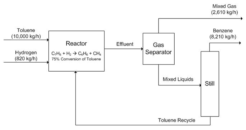
The simplest type of process diagram, a BFD is a superficial view of the process or plant and will show the overall picture with the flows of raw materials and products being shown, but without any chemical equipment information.
BFD is very useful in the early stages of design of a new process or plant without the cluster and detail of a PFD or P&ID, and it makes choosing between options much easier. Another benefit of BFD is it allows the reader to get a feel for the exiting process and when drawing a new process, a BFD is a starting point before starting the more detailed PFD.
 Figure 2: BFD showing equipment and streams with labels (Turton, 2012).
References
Turton R, B. R. (2012). Analysis, Synthesis, and Design of Chemical Processes Fourth Edition. Upper Saddle River: Pearson.

Dr. Adam Zaidi, PhD, is a researcher at The University of Manchester (UK). His doctoral research focuses on reducing carbon dioxide emissions in hydrogen production processes. Adam’s expertise includes process scale-up and material development.’


