Pressure Drop Caused By Valves and Fittings
In part 1 the tutorial goes over pressure drop in pipelines. Just to recap pressure drop arises due to skin friction and forms friction. Non-separated boundary layers causes skin friction (the roughness of the pipe causing shear within the boundary layer of the fluid) whereas separated boundary layers cause form friction (geometrical characteristics of the piping system are piled up causing localised losses).
Simply put, pipe pressure drop is due to skin friction. But in a pipeline with valves and fittings pressure drop is mainly due to form friction. The pipelines may be connected to equipment and again pressure drop occur due to the specific piece of equipment. This tutorial is focused on pressure drop in valves and fittings only.
In order to account for pressure drop due to valves and fittings, various methods are used The most common among them is:
- K values or Head Loss Coefficient.
- Equivalent length method.
1. K values or Head Loss Coefficient Method
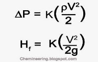
Where:
Hf = Head Loss
K = Head Loss Coefficient
V = Average Velocity of fluid
g = Acceleration due to gravity
= Density of fluid
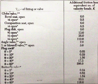
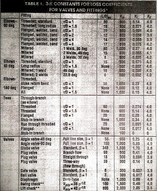
Depending upon the type of valves and fittings, various K values are available, which can be seen in the table below:
K values that are subject to change, then the pipe diameter can be calculated as follows:
Once determining the appropriate K value for your pipe, it can be substituted back into the first equation to determine the pressure drop or headloss
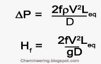
2. Equivalent Length Method.
Where:
f = Darcy’s Friction Factor
D = Internal Diameter of the pipe
Another method that is widely used in calculating pressure drop is the equivalent length method. For every valve and fitting particular L/D, equivalent length value is available in the previous table. To find the equivalent length, multiply the L/D value with the diameter and insert this value in the given formula, in place of Leq.
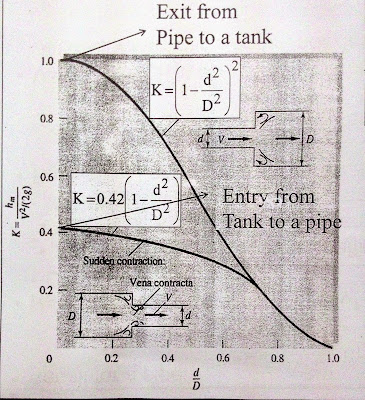
Similarly, for contraction and expansion losses you need to consider the k value as per the following formula.

Hassan graduated with a Master’s degree in Chemical Engineering from the University of Chester (UK). He currently works as a design engineering consultant for one of the largest engineering firms in the world along with being an associate member of the Institute of Chemical Engineers (IChemE).

