Batch and Levenspiel Plots
A Batch reactor plot is a graphical representation of the volume of an isothermal system.

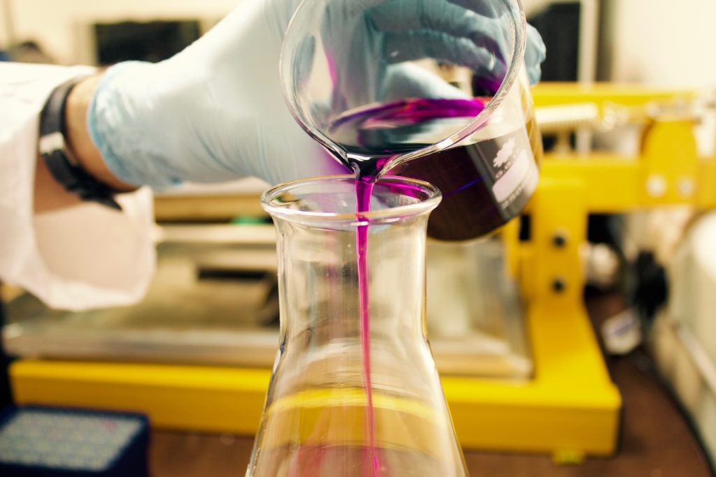
General shape of a Batch Reactor (Advanced Energy Materials Processing Laboratory, 2020)
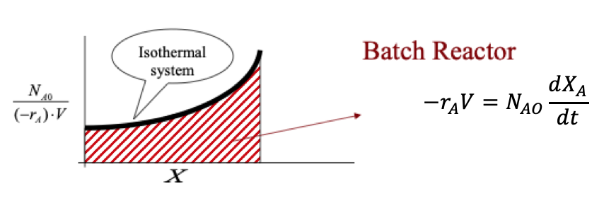
Batch reactor plot (Advanced Energy Materials Processing Laboratory, 2020)
A Levenspiel plot is a representation of the continuous flow reactor; CSTR and PFR design equations as a function of conversion and is used to determine the volume of the reactor.
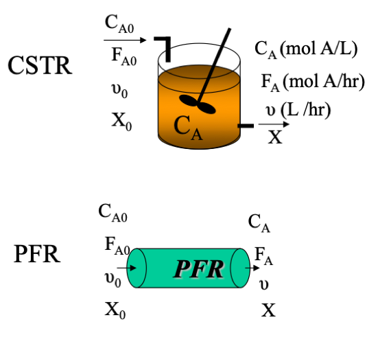
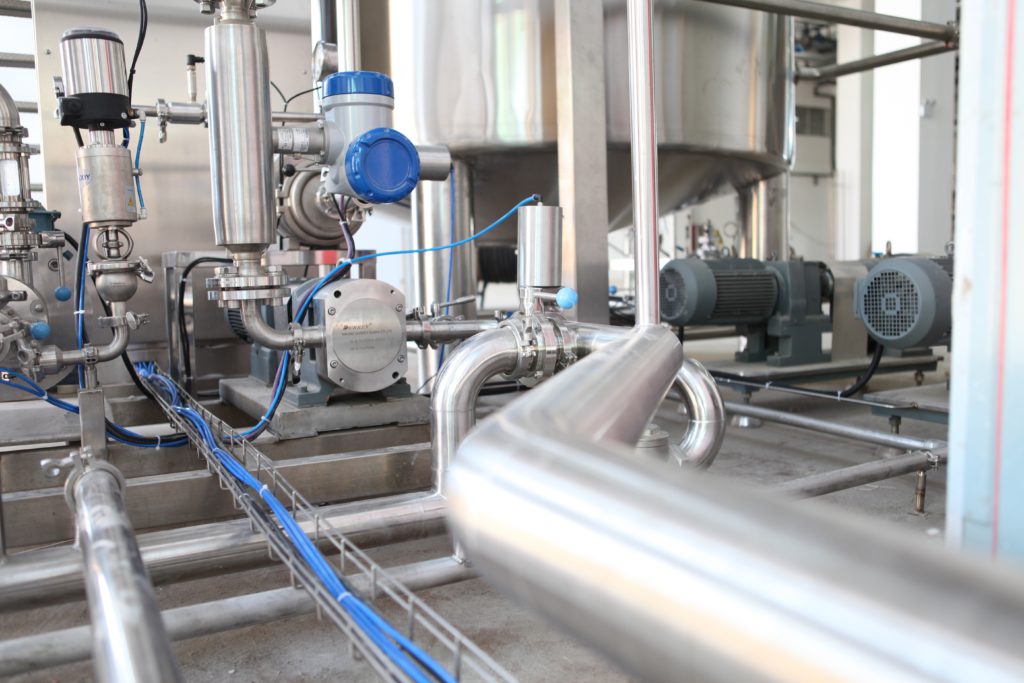
Shape of CSTR and PFR (Advanced Energy Materials Processing Laboratory, 2020)
PFR and CSTR Levenspiel Plot Comparison
The rate used for the CSTR is evaluated at the exit stream conditions while for the PFR the rate used is integrated over a range of conditions and we can solve this using Simpsons composite rule,
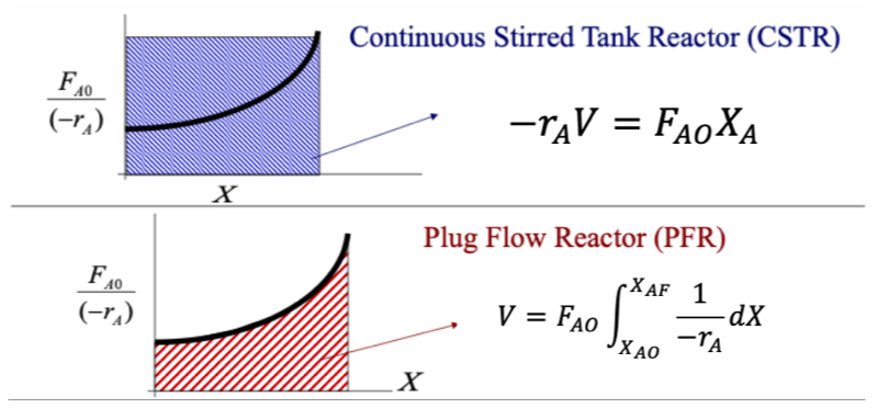
CSTR and PFR Levenspiel plot (Advanced Energy Materials Processing Laboratory, 2020)
- PFR requires a smaller volume than the CSTR for a given conversion
- When the reaction speed increases for a CSTR the Levenspiel plot will curve downwards as the conversion changes and will require a smaller CSTR volume.
Levenspiel Plot For Reactor In A Series Arrangement
PFR in series act as one large PFR and if the density is constant then the residence time is just the space time at the inlet conditions. For a CSTR multiple CSTRs in series require a smaller volume as a CSTR is evaluated at the output conditions and will make a series of CSTR’s smaller than one large CSTR, as when using multiple CSTRs the first tank operates at a lower conversion so the concentration of reactants will be higher so the rate will be greater and the volume required will be smaller.
CSTRs in series get close to the performance of PFR and the smaller the CSTRs the closer they get, but financial costs and available space and other factors make having lots of small CSTRs not practical when one PFR can be used.
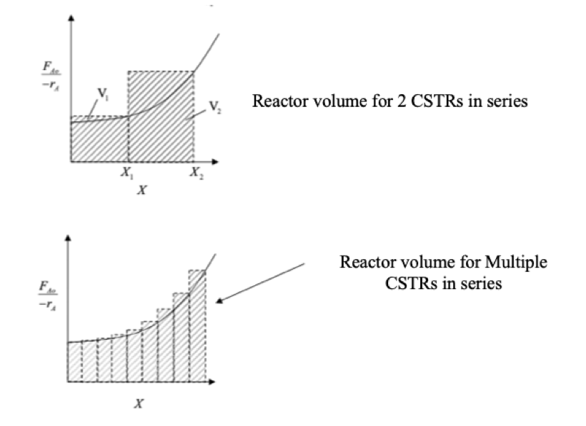
CSTR Levenspiel plot in series (MIT, 2007)
Parallel Reactors
Parallel reactors for equal-sized flow reactors, the feed stream is split evenly between the reactors. Parallel reactor arrangement is used for CSTRs as the reactors will be operating at the lowest conversion will be better to operate in series. For PFRs this arrangement behaves as one large PFR and is a common arrangement as used in industry or in Labourites.
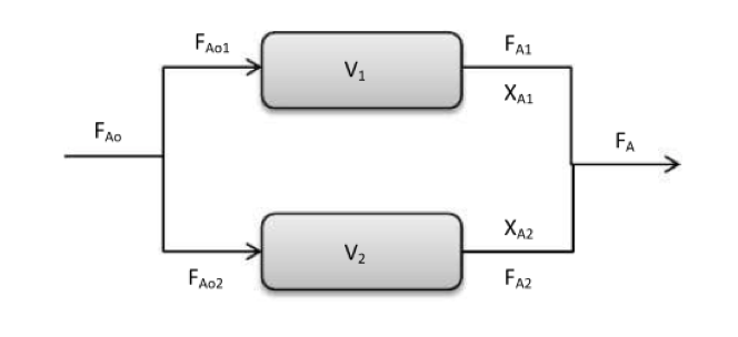
PFR in a parallel arrangement (Santofimio, 2020)
PFR With Recycle
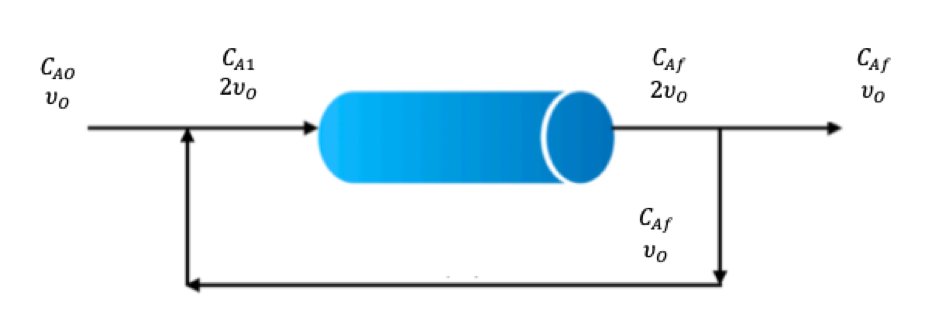
Unreacted reactants can be recycled from the PFR exit stream, we define a recycle ratio, R when it is equal to zero (R = 0) then we have standard/normal plug flow and as R increases we develop mixed flow and the PFR starts to resemble the behaviour of a CSTR.
R = Volume of fluid recycledVolume of fluid leaving PFR
(1.11)
We will be adding two new terms, single-pass conversion XS and overall conversion XO, the equations are below and have used species ‘A’ to represent the species used.
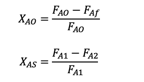
Single-pass conversion shows the fraction that is converted when it goes through the PFR once and overall conversion is the fraction converted in the final stream from the total inlet flow.

PFR with recycle diagram (Cheggstudy, 2020)
PFR with recycle is a difficult concept to get your head around and has a lot of keywords, that can trip you up if you don’t pay attention them, the best way is to do an example whilst looking at the answers and see what steps to do to solve this type of question in an exam, if you can do this example exam question without looking at the answers it will be extremely impressive!
Example – PFR with recycle (typical exam question)
In a PFR with recycle a reaction that is elementary and, in the liquid phase takes places, with an R = 1 and a conversion of 2/3, what is the conversion if there is no recycle stream?
References
Advanced Energy Materilas Processing Laboratory. (2020). CHE 309: Chemical Reaction Engineering. Retrieved from Advanced Energy Materilas Processing Laboratory: http://aempl.kist.re.kr/wp-content/files/Lecture-5_Ch2.pdf
Cheggstudy. (2020). Question: Problem 3: Recycle Reactor. Retrieved from Cheggstudy: https://www.chegg.com/homework-help/questions-and-answers/problem-3-recycle-reactor-farmer-michael-process-setting-recycle-reactor-farm-reaction-tak-q26913611
MIT. (2007). PFR vs. CSTR: Size and Selectivity. Retrieved from MIT: https://ocw.mit.edu/courses/chemical-engineering/10-37-chemical-and-biological-reaction-engineering-spring-2007/lecture-notes/lec09_03072007_w.pdf
Santofimio, D. S. (2020). Parallel Reactors.docx. Retrieved from Scribd: https://www.scribd.com/document/242835751/Parallel-Reactors-docx

Dr. Adam Zaidi, PhD, is a researcher at The University of Manchester (UK). His doctoral research focuses on reducing carbon dioxide emissions in hydrogen production processes. Adam’s expertise includes process scale-up and material development.’


